By: John Peterson and Scott Barney of Endicott Research Group, Inc.
Although there are different types of backlights (light sources) which are currently used for backlighting the latest Liquid Crystal Display modules, this paper will primarily fo- cus on cold cathode fluorescent tubes (CCFT) which are currently the light source of choice in most LCD modules. The intent of the paper is to familiarize the reader with some potential prob- lems and concerns associated with lighting CCF tube(s) and cover some of the common problem areas which have been prevalent over the last few years.
Cold Cathode Fluorescent Tube Parameters
Starting or Discharge Voltage is the mini- mum voltage required to “start” or ignite the tube (CCFT). This is generally expressed as a mini- mum rms voltage at some ambient temperature (generally the minimum temperature for the dis- play or tube).
The starting voltage is the primary pa- rameter which determines “end of life” for the tube and therefore the usefulness of the LCD module. If a voltage less than the minimum start- ing voltage is applied to the tube it will not light. The starting voltage of most CCF tubes is both time and temperature dependent. The older and colder the tube, the higher the starting voltage. Generally the minimum starting voltage specifi- cation is tied (directly or indirectly) to a life specification for the CCF tube(s) and the LCD module.
The output voltage of the inverter, mea- sured at the CCF tube, must be equal to or greater than the minimum starting or discharge voltage specified at cold temperature and maximum life of the CCF tube. Since the starting voltage re- quired by the CCF tube increases with time this relationship must be validated during the design stage of the system. This can not be empirically tested since the starting voltage of an aged CCF tube can be more than 50% higher than a new CCF tube.
Tube Current is the prime mover in con- verting electrical power into brightness. The brightness of any given CCFT is directly pro- portional to the rms tube current. The tube current as specified by the tube or display manufac- turer provides a benchmark for determining acceptable display brightness and indirectly the usable tube life. A general rule of thumb which is commonly used is; tube life is a square of the tube current (above nominal). If the tube current is increased to 20% above nominal then the tube’s useful life could decrease by 40% (reference to the stated tube life at nominal tube current). However, greatly exceeding the nominal or maxi- mum tube current can produce nonlinear and unpredictable life characteristics. Also exceed- ing the recommended tube current can produce excess heating which can cause discoloration of the display around the location of tube, affect- ing the overall appearance of the display.
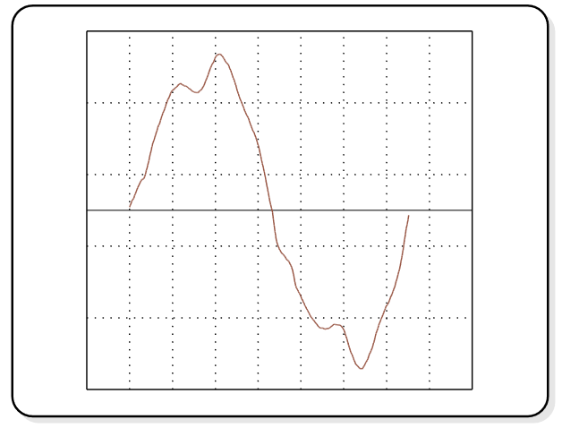
Figure 1: A typical output current waveform
Monitoring the current through the tube(s) can provide a useful indication of the approxi- mate tube brightness and can be very useful in “closed loop” dc to ac inverters.
Operating Voltage is the voltage across the tube after the tube has been lit. Generally the operating voltage is generated not applied. Electrically the tube looks similar to an ac zener diode dropping a predetermined voltage (deter- mined by the length and diameter of the CCF tube) with the actual voltage dropped across the tube decreasing slightly as the current through the tube is increased.
Although the operating voltage of the tube is somewhat uncontrollable this is still an im- portant parameter in the design or selection of a matching dc to ac inverter. The operating volt- age is a key design parameter in the design of standard dc to ac inverters and any inverter de- signed or selected for the wrong operating voltage can provide unsatisfactory and unpredictable results.
Frequency generally has no effect on the brightness, efficiency or life of the CCF tube, however the frequency of the voltage and cur- rent applied to and through the tube can have a major factor in the compatibly between the tube and the display, graphic engine and graphic in- formation displayed on the LCD module. The operating frequency of the inverter should be chosen to be completely compatible with the LCD module and graphic material used and dis- played in the system.
Higher frequencies can put restrictions on the packaging and interconnecting lead ca- pacitance between the inverter and the CCF tube.
Waveform, both current and voltage, can not only affect the performance of the tube but can generate unacceptable radiated electrical noise which might have adverse effects on the rest of the systems and be very costly to fix or remove for agency approvals and certifications. A properly designed and selected inverter can minimize the waveform distortion created by the dynamic nature of the tube and provide an in- verter CCF tube combination with minimum impact to the system and the surrounding envi- ronment. Although the dc to ac inverter produces a pure sine-wave the dynamic nature of the CCF tube distorts both the output current and output voltage. A typical CCF tube, inverter driven, waveform is illustrated in figure 1.
General Application Information
Dimming. There are two basic methods for dimming the CCF tubes used to backlight LCD modules. The first is an analog approach which simply reduces the current through the tube(s) by directly or indirectly reducing the input voltage to the inverter. The second, more of a digital approach, is pulse width modulation. Pulse width modulation controls the brightness of the tube(s) by turning the inverter (and there- fore the tubes) on and off very fast and governing the brightness by the controlling the on time with respect to the off time (duty cycle).
Analog dimming by reducing the tube current can be very effective when applied over a fairly narrow brightness range. Two primary areas of concern are guaranteeing proper start- ing voltage upon power up and maintaining minimum tube current through the tubes.
Any technique used to reduce the tube current by directly or indirectly reducing the input voltage of the inverter must insure the input starts at nominal for a sufficient amount of time during power up to light the tube at minimum tempera- ture and maximum tube life. This can be accomplished very nicely using a closed loop system that adjusts the input voltage after sens- ing the tube current. CCF tubes have a minimum tube current which must be maintained for proper operation. If the tube is operated well below this minimum the tube can light unpredictably or permanent damage can occur to the electrodes in the tube. This can shorten the useful life of the tube.
Pulse width modulation is a very straight forward method for controlling the brightness of CCF tube(s). The inverter is turned on and off (using the input or an enable/disable line) to control the brightness. The “on” duty cycle is increased to increase the brightness and is de- creased to decrease the brightness. One of the major advantages of pulse width modulation is the tube is always fully “on” or fully “off” and full starting voltage is always applied to the tube(s) (assuming nominal input voltage is present at the input of the inverter).
The frequency of the pulse width modu- lation signal (usually faster than the frame rate of the LCD, and generally less than 1 kHz) needs to be carefully selected to avoid any optical in- terference with the LCD module and the software or graphics being generated. A review of the LCD specifications will generally determine any potential frequencies of conflict. A simple sweep with a function generator will highlight any potential software or graphic conflict.
Since the brightness is now controlled by a digital pulse stream with an adjustable pulse width; interfacing the inverter to the systems micro can be simple and straight forward elimi- nating the need for “electronic” potentiometers and/or D to A converters. Also since the inverter is always operated at full load and nominal in- put voltage the efficiency of the entire systems can be quite high under any dimming condition.
The low inverter input current to full load input current action caused by the lower fre- quency pulse width modulation signal (usually well in the audible range) can cause audible noise or hum to be generated by any magnetic compo- nents which may be in series with the input in the inverter. These components should be prop- erly coated or sealed to avoid this problem. Larger input filtering capacitors can also reduce this situation.
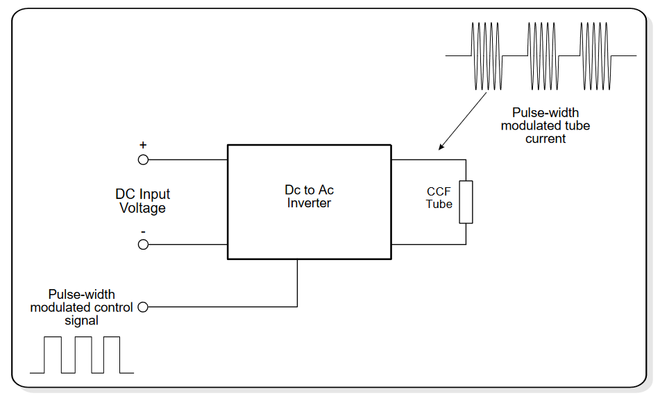
Figure 2: Simplified diagram of a pulse width modulated dc to ac inverter
Interconnection Pitfalls
Generally the CCF tube(s) are placed in a low voltage low power environment and often the high voltage and high frequency requirements of the CCF tube(s) are overlooked. Following are some common packaging reminders that help to avoid some problems down the road:
HIGH VOLTAGE. A CCF tube needs high voltage. The starting voltage is generally over 1,000 volts and the operating voltage is generally between 200 and 500 volts rms. Even if proper spacing is not being dictated by agency approvals care should be used in the selection of wiring and connectors. A good rule of thumb is to match the spacing that came on the LCD module. Usually this spacing is adequate for agency approvals and is certainly enough for proper operation.
High Frequency. The operating fre- quency for the CCF tube can be fairly high and the general make up of the inverter circuit can make the wiring between the inverter output and the LCD module tricky. In series with the invert- ers output (internally) is usually a small capacitor (15 pf – 39 pf) (see figure 3). This capacitance becomes a fairly high impedance which is al- ways in series with the tube. Any stray capacitance produced by the inverter-to-display wiring can reduce the starting voltage applied to the tube(s) and reduce the life and brightness of the tube(s). The inverter should be located as close as possible to the CCF tube(s). The wir- ing used should produce low capacitance. Generally the thick walled wire which is used on most LCD modules is used to produce low capacitance not high voltage protection. Oper- ating the inverter in a non-isolated configuration can add to the stray capacitance on the output therefore reducing the starting voltage applied to the CCF tube(s). If this is done for noise re- duction purposes, it must be taken into account in the design so adequate starting voltage is maintained.
Circuit Operation
Most CCFT dc to ac inverters are tuned switchers designed to produce a specific volt- age, frequency and output current when a specified tube is connected to the output. The classic current-fed two-transistor inverter has a tuned resonating output, tuned resonating input and inductive dc input that allow excellent power transfer and high operating efficiency.
This type of circuit inherently produces a pure sine-wave output, but the voltage and current waveforms are both distorted when they are applied to a CCF tube, which is a highly nonlinear device.
ignited. This high series internal impedance is responsible for a “constant current” output which is typical in this type of circuit. As a result this circuit produces its nominal design output cur- rent under almost any load condition – from a very high impedance to a “dead” short circuit.
Since the output of this type of circuit is an “ac constant current source” the output will supply its nominal output current into a short circuit. Under a short circuit condition the input current drops dramatically since the input power into the inverter is now just supplying the in- verter losses which are generally very small when compared to the nominal input power.
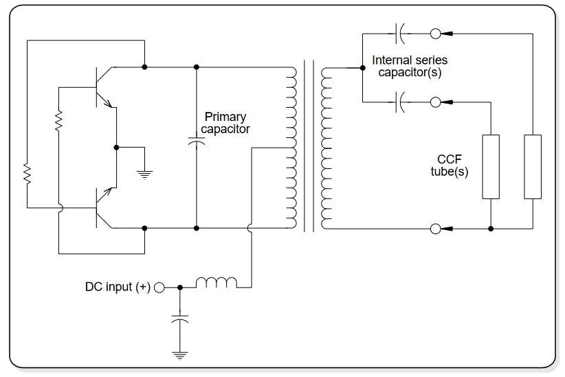
Figure 3: A basic diagram of the classic current-fed two transistor dc to ac inverter
The transition from starting voltage to operating voltage in this circuit is implemented by a small internal series output capacitor which serves as the ballast, providing impedance, and allowing proper tube current after the tube has bination of high voltage, low current, and high frequency makes conventional test equipment and methods almost useless. Any external re- sistance, impedance, or ground loop can dramatically alter the operation of the dc to ac inverter and distort the measurements being ob- served.
Let’s look at some specifics. The im- pedance of a typical 2.5 Watt 6 inch CCF tube is 50,000 to 70,000 ohms. The small internal capacitor usually found in series with each out- put of the inverter offers an impedance that is typically three times that of the CCF tube to which it is connected. Even a voltmeter with a 10 Megohm input impedance can load the out- put enough to render the reading meaningless. An oscilloscope can be even worse. The approximately 20 picofarads of scope probe ca- pacitance presents a relatively low 250 Kohm of impedance at 30 kHz.
There are straight forward methods for measuring the voltage, frequency and current of an operating CCF tube. One method is to mea- sure the true rms current trough the CCF tube using a broadband current probe – such as the Tektronix CT-2 – that magnetically detects the ac current without appreciable circuit interac- tion. The probes output can be fed into a appropriate true-rms voltmeter or digital oscil- loscope capable of calculating true rms at the nominal current frequency.
The output voltage to the tube can be measured with a dual-channel oscilloscope and two low-capacitance (< 2.5 pf) scope probes. The oscilloscope should be connected differen- tially, with the probe grounds connected and floating. Channel A should be added to the in- verse of channel B to produce the complete waveform on the oscilloscope (see figure 4). The rms voltage value can be calculated by the digi- tal oscilloscope or measured with a true rms voltmeter connected to the oscilloscope’s verti- cal-signal output jack (if available). Although this method loads the CCF tube and inverter
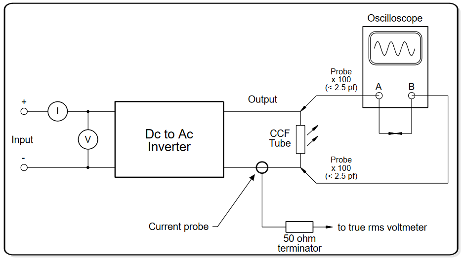
Figure 4: Basic test setup for measuring the output voltages
minimally, there may still be enough loading to change the operating voltage slightly, especially in higher frequency inverters. Even a slight change in the brightness of the tube – or display – is an indication of some interaction between the inverter or tube and the measuring equipment.
The no-load – starting voltage – of the inverter is the most difficult parameter to mea- sure accurately. The slightest external impedance can reduce the inverter’s no-load output volt- age. Nonetheless, the setup used to measure the operating voltage can be used to measure the no-load output voltage fairly accurately. The length of the test leads and wires should be mini- mized to reduce stray capacitance. Monitoring relative differences in the input current with and without the measuring equipment connected in- dicates the relative magnitude of effects of the external equipment.
Conclusion
CCF tubes are currently the best light source for the modern transmissive LCD mod- ules currently being designed into many applications. They offer high brightness and high efficiency which makes them an ideal choice for portable applications. It is hoped that some of the information in the paper will help avoid any misapplications which could lead to product or system failure.
Authors’ Biographies
John Peterson is the Chief Engineer of Endicott Research Group, Inc. and has over 20 years of experience in magnetically based power supplies used throughout the information dis- play industry.
Scott Barney is the Sales Manager of Endicott Research Group, Inc. and has an extensive background in LCD module applications.